IR Translator

Pre-waffle
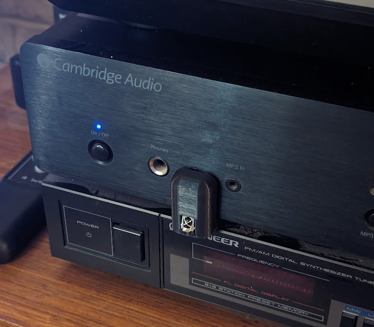
Our living room setup is an old 1080p Samsung dumb TV, a Chromecast with Google TV, with sound feeding into a Cambridge Audio amp via a DAC by optical. This set-up gives fantastic audio for the money compared to a soundbar or even a receiver, but with no HDMI ARC the downside is control of the amp volume which until now has been clumsily through it's own dog-chewed remote.
Chromecast with Google TV (stupid name) does come with a remote which mostly works via some kind of microwave (I know because it works when I sit on it) but also has an IR transmitter. You can program the remote to control to a number of pre-set IR codes which probably cover most TVs (including ours) and receivers but not a relatively uncommon amp.
When you set the TV to output sound via only optical, there is no volume control, and the volume buttons on the TV remote do nothing.
Wouldn't it be great if the amp would respond to the TV’s volume IR codes? Then I could program the Chromecast remote to transmit the TV volume IR codes, and the Chromecast remote and the TV remote would both control the amp volume. That's exactly the niche problem I'm trying to solve here, but an IR Translator probably has applications to a wider range of similar problems.
The requirements
As a true systems engineer should, I'll start with a list of verifiable requirements:
The solution
Basis
The obvious solution for this is Arduino, which is exactly what I used. I can prototype on a full-size Uno and then move to a Nano for the final product. I could have made the whole thing smaller with an ATTiny or other microcontroller (with a lot more faff) but the Arduino Nano is small enough to hide under the amp so it doesn't matter. Arduino Nanos are only a few quid each.
Software
This was surprisingly easy. In fact so easy it was pretty unsatisfying as a first proper Arduino project. Perhaps I'm showing my inexperience here, but I expected to be writing code to poll the IR sensor at some relatively high frequency and decoding that into a number. Turns out someone's done all that hard work for me.
I've used the library IRRemote.h which can be used to constantly scan for IR codes, and also to transmit. It's then a simple matter of if statements to transmit a corresponding code to the incoming code.
To find the codes for both recieving and transmitting, I used a section of code to display any recieved IR code in hex on the temporary LCD screen. So it's as simple as pointing both Hi-Fi and TV remotes at the receiver in turn, pressing the appropriate buttons and noting down the relevant hex codes to put into the software.
Obviously this approach requires faff with the LCD screen and re-writing the code to change the codes if I ever need, but on-the-fly reprogramming wasn't one of the requirements.
I've commented out the code for the LCD screen in the final build of the code because I'm under the illusion that will make it run faster and maybe consume less power (see requirements P-R-003 and P-R-004).
The code can be found on GitHub:
Hardware: electronics
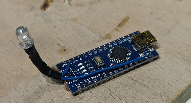
Minimalism was key here (see requirement P-R-002). Therefore no space for the bulky IR receiver that comes with the Arduino kit. Luckily most IR receivers are wired the same, with anode, cathode, and a single output which for Arduino purposes is logic-level. Easy.
Output is easy too; an IR LED and current-limiting resistor.
The second output is the standard LCD screen which is plugged in temporarily for finding the codes. If you can't be bothered with this then you could output the IR codse to the PC via serial.
Pinouts of all these are at the top of the code. The circuit is simple enough that I won't bother with a diagram.
Hardware: enclosure Minimalism was also key here (see requirement P-R-002). I've chosen to hide the Arduino board under the amp for minimalism, and as it's protected under there I won't bother enclosing it. In my case the unit in the stack beneath the amp is an old FM tuner which has a plastic case so no need to worry about shorting the exposed terminals underneath. If you were worried, you could always heatshrink the board.
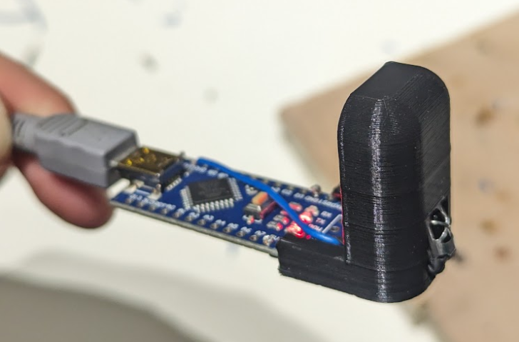
Therefore the enclosure serves two proposes: holding the receiver and LED in a good place, and acting as a barrier between the primary and secondary IR signals.
3d printing is the obvious/lazy solution to the owner of a cheap 3d printer.
The enclosure interference fits onto the edge of the Arduino Nano PCB, and the LED and its resistor are wired up with the help of some small pieces of wire and heat shrink.

To keep this as small as possible, the IR receiver feeds through the enclosure and therefore needs to be soldered after the enclosure is mounted on the board. The housing turned out to be pretty tight on the receiver which is probably because I have a habit of cranking up print speed arbitrarily and so the printer probably overshot the sharp corners around the LED.

The housing is designed to be printed right-way-up from PLA with minimal supports (assuming a printer that can handle 45° overhangs).
Results and verification

Make your own
Enclosure
Software
You'll also need:
Tools:
Good luck!
-----
License of code and enclosure model: Creative commons share alike. Non-commercial.